Tilt-Back Tire Changer Installation: How to Check Rear Clearance
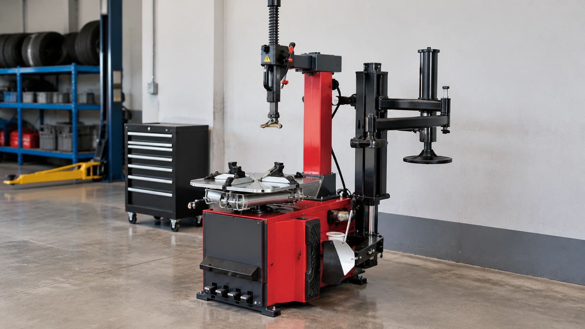
When planning a workshop installation for a tilt-back tire changer, buyers should verify the space required for the machine’s moving components, not just its static footprint. Rear clearance must accommodate the movement of the tilt-back assembly throughout its operating path, while the surrounding layout must also allow the operator to use the machine and access it for maintenance. The required distance depends on the exact model, configuration and manufacturer’s installation requirements; there is no single rear-clearance value for every tilt-back tire changer.
For automotive equipment distributors, tire service businesses and workshop planners, the practical task is to compare the machine’s installation and movement requirements with actual site dimensions before ordering. CHENTUO’s electric/pneumatic wheel-clamp tilt-back tire changer is a relevant product to assess, but the final layout should be based on documentation for the specific model rather than assumptions from a product photograph.
1. Why Is the Static Footprint Not Enough for a Tilt-Back Tire Changer?
The static footprint describes the space occupied by a machine in a particular position. It does not necessarily describe the full space required when a component moves. If the machine is installed too close to a wall, column or other fixed object, the movement path may be obstructed even when the machine fits within the available floor area.
Distinguish the Machine Footprint from the Movement Envelope
- Static footprint: where the machine sits on the floor in its reference position.
- Movement envelope: the space occupied by moving components throughout their operating travel.
- Operating space: the area needed to position a wheel, operate controls and perform the intended work.
- Maintenance access: space required to inspect or service the equipment according to the manufacturer’s instructions.
These areas are not interchangeable. The correct movement envelope must be established from the manufacturer’s drawing or model-specific documentation. A photograph showing the column in one position is not enough to determine the full operating path.
Identify Which Components Move During Tilt-Back Operation
Identify the moving components of the selected model and obtain documentation clarifying the machine’s reference installation position, initial and final positions of the tilting assembly, movement dimensions and stated clearance requirements. If the quoted configuration differs from the reference drawing, confirm the difference. Do not infer movement angle, maximum rearward extension or minimum wall distance from a photograph.
2. How Should Buyers Measure the Available Space Behind the Machine?
Rear-clearance planning should begin with the proposed machine location and a defined measurement reference. Measuring from an arbitrary machine edge can lead to incorrect conclusions if it differs from the reference used in the installation drawing.
Establish the Machine Position and Measurement Reference
Mark the intended installation position on the workshop layout and use the manufacturer’s specified reference points where available. Record the machine’s position and orientation, distance to the rear wall or nearest fixed obstruction, locations of columns and adjacent equipment, and any floor or utility constraints.
The site survey and machine drawing should use compatible reference points. If the drawing defines the machine’s rear boundary differently from the buyer’s assumed point, the measurements cannot be compared directly without adjustment.
Check the Entire Movement Path, Not Just the Final Position
A clearance check should consider the moving assembly throughout its travel, not only when the column is upright or fully tilted. An obstruction may not interfere with the initial position but may intersect the movement path at an intermediate position.
- Check whether the movement path intersects a wall or column.
- Check whether adjacent equipment occupies part of the required envelope.
- Check doors, cabinets and other fixed objects.
- Confirm that the proposed installation position matches the reference drawing.
- Verify any additional clearance specified by the manufacturer.
If only static machine dimensions are available, the rear-clearance review remains incomplete. Request movement dimensions or written installation guidance instead of estimating from a photograph.
3. Which Workshop Obstacles Should Be Checked Before Installation?
Rear clearance is not determined by the wall alone. Workshop layouts may contain fixed or semi-fixed obstacles that affect the movement path and the space available for operation.
Check Walls, Columns, Doors and Adjacent Equipment
Identify rear walls, structural columns, doors and tracks, fixed cabinets, adjacent tire-service machines and shelving that cannot be moved during normal operation. The key question is whether an obstruction enters the required movement envelope, not simply whether it looks close in a floor plan.
Consider Utilities and Maintenance Access
Review electrical connections, pneumatic connections and other site services against the manufacturer’s installation instructions. Distinguish movement clearance from operating space and maintenance access; sufficient rear clearance does not automatically prove the machine has enough space for normal use or service.
| Space requirement | Main question | Information needed |
|---|---|---|
| Movement clearance | Can the tilt-back assembly complete its required travel without interference? | Model-specific movement or clearance information |
| Operating space | Can the operator position the wheel and use the machine as intended? | Operating instructions and workshop layout |
| Maintenance access | Can the specified inspection and maintenance tasks be performed? | Manufacturer’s service instructions |
4. How Should Buyers Check the Space Required for Operation and Servicing?
Separate Movement Clearance from Operator Working Space
Movement clearance concerns the physical path of the moving assembly. Operator working space concerns the area needed to handle wheels, operate controls and perform the intended tire service tasks. Identify the operator’s normal working position and check whether adjacent machines, walls or storage areas interfere with the required work.
Confirm Access for Inspection and Maintenance
Maintenance access should be checked against the manufacturer’s documentation. Confirm which areas must remain accessible for routine inspection, whether any component needs additional space for removal or adjustment, whether the proposed position allows access to service points, and whether surrounding equipment must be moved for maintenance. If the public product information does not specify these requirements, ask the supplier rather than inventing a distance.
5. How Should Buyers Verify a Tilt-Back Tire Changer Before Ordering?
Prepare a Workshop Layout for Supplier Review
Prepare a dimensioned layout showing the intended machine position and orientation, distance to the rear wall or fixed obstruction, nearby columns and equipment, operating space, utility constraints, exact model and configuration, and site photographs or a dimensioned floor plan.
This allows the supplier to review the proposed location against the product’s actual requirements rather than provide a general assurance that the machine will fit.
Request Model-Specific Clearance Confirmation
For CHENTUO’s electric/pneumatic wheel-clamp tilt-back tire changer, request the installation drawing or written confirmation of rear-clearance requirements for the exact configuration being quoted. Confirm the reference position, dimensions defining tilt-back movement, clearance from fixed obstructions, additional operating or maintenance space and consistency with the proposed workshop layout.
If a drawing does not show the movement envelope clearly, ask the supplier to identify the relevant dimensions. A quotation listing electrical options or other product features does not automatically resolve installation-space questions. If the configuration changes, repeat the clearance review.
6. What Should Buyers Do If the Available Rear Clearance Is Limited?
Compare the Required Movement Envelope with the Actual Site
Overlay the manufacturer’s movement information on the measured workshop layout. Identify the specific obstruction and the point at which it conflicts with the required movement. If information is incomplete, do not assume the machine can operate with reduced clearance; obtain clarification before accepting the location.
Confirm Any Proposed Layout or Model Change
If the layout cannot meet the confirmed requirements, assess whether the equipment position can be changed or another configuration should be evaluated. Check any change against the complete installation arrangement, including operating access and utilities. If a different model is proposed, obtain its own installation information; do not transfer clearance requirements from another machine.
7. What Should Buyers Record Before Approving the Installation Layout?
| Verification item | Evidence to retain |
|---|---|
| Exact machine model | Product designation and quoted configuration |
| Installation position | Dimensioned workshop plan |
| Rear obstruction distance | Site measurement with a clear reference point |
| Movement envelope | Manufacturer’s drawing or written confirmation |
| Adjacent obstructions | Site plan or annotated photographs |
| Operating space | Layout checked against operating instructions |
| Maintenance access | Applicable service documentation |
| Unresolved issues | Written clarification from the supplier |
This record should reflect the actual installation, not just a preliminary catalogue comparison. If the workshop layout or machine configuration changes, review the affected dimensions again before installation.
Conclusion
Installing a tilt-back tire changer requires more than checking its static footprint. Buyers must establish the machine’s movement envelope, measure available rear clearance from the correct reference point, identify fixed obstacles and verify the space needed for operation and maintenance.
For CHENTUO’s tilt-back tire changer, the public product page provides a starting point for identifying the equipment, but the exact rear-clearance requirement should be confirmed using model-specific installation information. A reliable purchasing decision depends on comparing that information with the actual workshop layout before the equipment is ordered.
If the installation drawing does not provide the necessary movement dimensions, request clarification from CHENTUO before approving the location. For product information, visit the CHENTUO tilt-back tire changer page and confirm the installation requirements for the exact model and configuration.