What Should Buyers Check on a Car Lift Installation Drawing?
A car lift installation drawing should be reviewed before the order is released, not only when the equipment arrives. The drawing helps buyers confirm whether the selected lift can physically fit the bay, accept the intended vehicle range, maintain safe clearances, connect to the available utilities and meet the site conditions required for installation. A lift can have sufficient rated capacity and still be the wrong choice if the columns, runways, platforms, vehicle envelope or service space conflict with the workshop. For B2B buyers, the practical sequence is: define the vehicle population, measure the real bay, review the exact model drawing, confirm floor and utility conditions, resolve deviations, then freeze the installation scope in the RFQ.
Why the Installation Drawing Belongs in the Buying Process
Many workshop-equipment purchases begin with capacity, lift type and price. Those are important, but they do not establish site fit. An automotive lift installation drawing connects the product to the building. It turns a general model choice into an installed-equipment decision.
The drawing should allow the buyer to answer concrete questions: Where will the posts or platforms sit? How much width remains around the vehicle? Can doors open? Does the approach path stay clear? Are there overhead obstructions? Is the power unit accessible? Can anchors, pits or other interfaces be prepared correctly? If these questions remain unresolved until delivery, the problem often becomes rework, relocation, installation delay or a reduced usable vehicle range.
CHENTUO lists multiple car-lift architectures in its Car Lifts category, including two-post, four-post and scissor arrangements. The installation check therefore has to follow the exact model and structure, not a generic drawing from another lift.
Measure the Real Workshop, Not Only the Building Plan
A nominal bay dimension is not the same as usable installation space. Before reviewing a car lift floor plan, measure from the finished floor to the lowest fixed obstruction and record the true clear width and length around the proposed lift position.
Common conflicts include beams, lighting, sprinklers, HVAC ducts, garage-door tracks, columns, wall cabinets, tire-service equipment, wheel-alignment hardware, electrical panels and vehicle circulation routes. A ceiling marked as 3.2 m on a building drawing may provide less usable height at the lift position because a door rail or service line hangs lower.
The buyer should mark these obstructions on the workshop sketch and send them with the RFQ. That lets the supplier compare the lift geometry against the actual installation envelope rather than an idealized empty bay.
Match the Vehicle Envelope to the Lift Layout
A correct garage car lift installation also depends on what the lift must raise. Vehicle weight is only one input. The supplier may also need the wheelbase, track width, overall height, tire width, ground clearance and any long overhang or unusual body equipment.
Those dimensions interact with the lift differently. Wheelbase and track influence runway or arm positioning. Ground clearance affects approach and pad access. Vehicle height affects overhead clearance when raised. Door geometry affects post location. A long van, pickup or SUV may fit the rated load but still create a bay-clearance or lifting-point problem that a smaller passenger car does not.
For mixed workshops, use a vehicle matrix instead of one representative car. Include the lightest common vehicle, the heaviest vehicle, the tallest vehicle and the longest-wheelbase vehicle expected in the bay. The selected lift should be reviewed against the boundaries of that population.
Two-Post, Four-Post and Scissor Lifts Need Different Drawing Checks
The installation drawing should be read according to lift architecture. Treating every car lift as the same rectangle on the floor hides important differences.
Two-post car lift installation
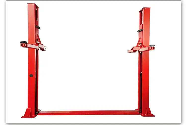
For a two-post layout, buyers should review column position, arm sweep, lifting-point reach, door opening space, vehicle centering, anchor pattern and any overhead or floor-plate structure. The CHENTUO two-post product page describes a double-column gantry lift with a 3500 kg capacity. That public product reference is useful for identifying the lift family, but the exact installation drawing and site requirements should still be requested for the selected configuration.
Column spacing that looks acceptable on paper can become restrictive if the vehicle door, mirror or body width is not considered. Arm reach also matters because the lift has to reach approved lifting points without forcing the vehicle into an unsuitable bay position.
Four-post car lift installation
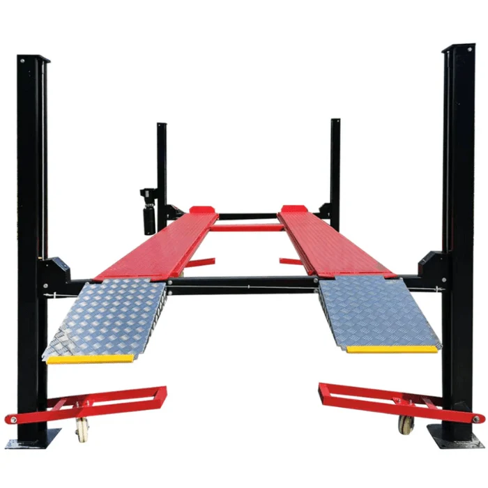
A four-post lift introduces runway length, runway spacing, approach ramps, wheelbase coverage and vehicle overhang. The CHENTUO CT609 listing identifies 4T/5T capacity options and a stated maximum lift height of 72.8 inches. Those figures describe parts of the product specification; they do not replace a dimensioned installation drawing.
The buyer should verify whether the intended vehicles fit the runways, whether there is room to drive on and off, and whether the raised vehicle envelope remains clear of the ceiling and surrounding equipment.
Scissor lift installation
Scissor arrangements shift the review toward platform size, lowered height, surface-mount or pit conditions where applicable, approach geometry and access around the raised vehicle. A compact footprint can solve one workshop problem while creating another if the platform contact arrangement does not match the service task.
Why Maximum Lift Height Is Not the Same as Required Ceiling Height
This is one of the most common drawing-review mistakes. A listed maximum lifting height is a product movement dimension. The building must accommodate the lift, the vehicle and the required clearance at the same time.
For example, the CT609 page states a maximum lift height of 72.8 inches. That number should not be treated as the required ceiling height. The raised vehicle sits above the runway or platform, and the vehicle body itself adds height. Door tracks, lighting and other obstructions can further reduce the available space.
A useful review therefore follows this logic:
usable vertical space → lift structure → raised platform/runway position → vehicle height → remaining overhead clearance.
If the remaining clearance is insufficient, the buyer may need a different lift architecture, a reduced working position, a different bay or a different vehicle-service policy.
Floor and Foundation Conditions Must Be Confirmed for the Exact Model
Car lift foundation requirements should never be copied from another model or another supplier. The floor has to support the installed equipment according to the selected lift’s approved installation requirements and local project conditions.
Before order release, the buyer should record the floor/slab condition, any pit or recess, slope, visible cracking, existing anchors and underground-service concerns. Then request the model-specific installation information from the supplier and have the site reviewed by the appropriate qualified party where required.
The important evidence is not simply “a foundation drawing.” Buyers should verify that the drawing identifies the exact model, anchor positions, structural interfaces, installation dimensions and any stated site-preparation conditions. If the drawing revision does not match the ordered model, the foundation work should not proceed.
Power, Hydraulic and Control Interfaces Belong on the Setup Checklist
A car lift setup is also an electrical and hydraulic installation task. Buyers should confirm the destination power supply, voltage, phase, frequency and control location for the selected product. Where hydraulic power units, hoses or control cabinets are supplied separately, the installation plan should show where they can be accessed without blocking vehicle circulation or maintenance.
Do not assume that the public product title defines every destination-market electrical detail. The order document should freeze the actual configuration. The same principle applies to cable routing, hydraulic hose routing, local disconnects, emergency controls and installer responsibilities.
What Should Buyers Check on the Installation Drawing?
| Drawing Item | Buyer Check | Why It Matters |
|---|---|---|
| Overall lift dimensions | Compare with real bay width, length and obstructions | Prevents physical fit conflicts |
| Column/runway/platform position | Compare with vehicle width, wheelbase and access | Confirms vehicle fit |
| Raised height | Combine with vehicle height and lowest overhead obstruction | Defines usable vertical envelope |
| Anchor or foundation layout | Confirm exact model and site interface | Prevents site-preparation mismatch |
| Power unit/control location | Check service access and operator movement | Avoids blocked controls and maintenance access |
| Electrical input | Match destination supply and installation plan | Prevents commissioning delay |
| Vehicle approach | Check ramps, doors and turning path | Ensures the bay is usable, not only installable |
| Safety clearance | Check walls, doors, beams and adjacent equipment | Reduces operating conflicts |
Product Drawing and Installation Drawing Are Not the Same
A product drawing mainly describes the equipment itself. An installation drawing should place that equipment into an installation context: anchor positions, clearances, approach space, utility location and surrounding-site requirements.
This distinction matters in distributor and project procurement. A catalog dimension may be enough to shortlist a model, but it is not enough to release construction work. The buyer should request the document that the supplier intends installers to use for the exact ordered configuration.
What Should Be Confirmed Before Installation Starts?
- Exact lift model and selected configuration
- Rated capacity and intended vehicle range
- Bay width, length and clear height
- Lowest overhead obstruction
- Vehicle height, wheelbase and track range
- Floor/slab condition and required site preparation
- Anchor, pit or platform interface as applicable
- Electrical supply and control location
- Hydraulic power-unit and hose arrangement
- Vehicle approach and exit path
- Operating and service clearances
- Current installation drawing revision
- Installer, buyer and supplier responsibilities
- Commissioning and acceptance checks
Build the RFQ Around the Site, Not Only the Lift Model
A useful RFQ should attach the workshop sketch, real clear dimensions, vehicle matrix, intended service tasks, floor information, available power supply and required documentation. Ask the supplier to return a model-specific drawing and identify any deviation between the proposed lift and the buyer’s site.
Buyers can review CHENTUO’s Car Lifts range first, then compare the selected product against the workshop. For a two-post project, the CHENTUO two-post lift page provides a product reference. Once the bay information is ready, submit the drawing and site data through the Contact Us page for configuration review.
The goal is not merely to confirm that a lift can be delivered. It is to confirm that the ordered equipment can be installed, approached, operated and serviced in the buyer’s real workshop without unresolved interface problems.