What Size Air Compressor Does a Tire Changer Need?
Size an air compressor for a tire changer by its delivered airflow at the required operating pressure, then check the shop’s busy-period demand, the compressor’s permitted duty cycle and its ability to recover after peaks. Horsepower and tank capacity alone cannot establish whether the machine will have enough air throughout a working session.
The most useful comparison is a demand profile rather than one headline rating. A tire changer may use air intermittently, while another tool draws from the same supply at the same time. For a shop adding CHENTUO tire changers, the following method connects those demands to compressor output and storage. The numerical example is hypothetical, not a specification for a CHENTUO model.
Start With the Tire Changer’s Air Demand, Not Its Motor Size
Identify which functions use air and how consumption is reported
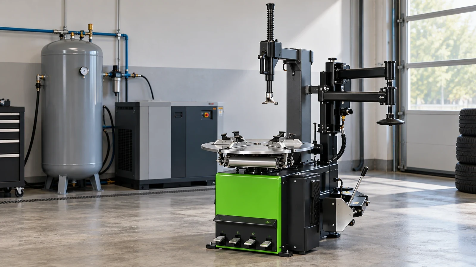
An electric turntable does not make a tire changer independent of compressed air. Depending on the configuration, clamping, bead-breaking, column movement or assist-arm functions may use pneumatic actuators even when a motor rotates the table. A machine with an air-driven motor presents a different load from an electric-drive configuration.
CHENTUO’s electric/pneumatic tilt-back tire changer with assist arm illustrates why electrical and pneumatic requirements need separate consideration. Its electrical power information is not a substitute for an air-consumption figure. Establish the supplied configuration before comparing it with a compressor.
The next question is what the consumption figure measures. These three descriptions require different calculations:
| Reported quantity | How it enters a demand estimate |
|---|---|
| Airflow while an action is operating | Multiply by the fraction of the selected period for which that action draws air to estimate its average contribution. |
| Free-air volume per complete cycle | Multiply by cycles per minute. Confirm which actions are included in a cycle. |
| Average airflow at a stated throughput | Use that average for the matching throughput; do not apply the same usage allowance a second time. |
Use a representative busy period, not only an average across a day that includes long idle intervals. Also identify short, high-flow events separately. A low average can conceal an event that causes a noticeable pressure drop each time it occurs.
Match Delivered Airflow to the Required Working Pressure
Separate machine inlet pressure, receiver pressure and tire inflation pressure
The tire changer’s specified inlet pressure range is the starting point. A compressor reaching a high cut-out pressure does not prove that the machine receives sufficient pressure while air is flowing. The supply must maintain the required inlet conditions through the distribution line and any regulator or air-treatment components.
Receiver pressure describes the air stored upstream. Machine inlet pressure describes the supply reaching the equipment. Tire inflation pressure describes the pressure inside the tire. None of these is a substitute for the other. Use the exact machine’s supply requirements and the separate tire-service instructions; a compressed-air inlet rating is not a tire inflation target.
Compare like-for-like flow ratings
Look for delivered airflow at the pressure the compressor will actually need to supply. A displacement figure describes a different quantity from usable output, and a rating at a lower pressure is not automatically valid at a higher one. A motor’s horsepower identifies its drive rating, not a universal amount of delivered CFM.
CFM means cubic feet per minute. SCFM expresses a flow against stated standard conditions; ACFM refers to actual conditions at a specified point. Free air delivery, or FAD, reports compressor delivery referred back to specified inlet conditions. These labels need their reference conditions, not just a matching unit symbol. Converting liters to cubic feet changes the unit; it does not reconcile different temperature, pressure or humidity references.
For a useful comparison, place the equipment demand and compressor output on a common reference basis. Then check that the output rating applies at a system pressure capable of maintaining the tire changer’s inlet requirement under load. Tank volume belongs in the later storage calculation, not in place of the delivered-flow figure.
Calculate Average Demand and Simultaneous Peak Demand
Average demand describes how much air the system consumes over time. Peak demand describes what it asks for when loads overlap. Both affect selection, but they answer different questions.
Consider the following hypothetical busy-period estimate. All flows use the same free-air reference conditions and are assumed to apply at the required working pressures. CFM values below are rounded unit conversions on that same basis. The example excludes leakage and other unlisted air consumers.
| Assumed load | Flow while operating | Use during the period | Average contribution |
|---|---|---|---|
| Tire changer pneumatic load | 300 L/min (10.6 cfm) | 40% | 120 L/min |
| Another shared tool | 200 L/min (7.1 cfm) | 25% | 50 L/min |
| Combined | 500 L/min (17.7 cfm) if both operate together | The percentages do not establish overlap | 170 L/min (6.0 cfm) |
Average demand = (300 × 0.40) + (200 × 0.25) = 170 L/min
The calculation gives an average, not a promise that demand never exceeds 170 L/min. If both loads operate simultaneously, they draw 500 L/min for that overlap. Its duration matters. If the workflow prevents simultaneous operation, adding both operating flows as a real concurrent peak would instead overstate that scenario.
Do not confuse tool use with the compressor’s permitted duty cycle
The tool-use percentages above describe consumption. The compressor’s duty-cycle limit describes how it is allowed to run. They are separate inputs.
Suppose a candidate compressor is permitted to deliver air under load for only 50% of its manufacturer’s specified evaluation period. In an ideal repeating cycle, covering an average demand of 170 L/min would require at least:
Loaded delivery = 170 ÷ 0.50 = 340 L/min (approximately 12.0 cfm)
This is a theoretical balance point for the stated assumptions, not a finished compressor recommendation. It leaves no allowance for leakage, air-treatment consumption or additional demand. The actual installation must also satisfy the manufacturer’s temperature, cooling, cycle-duration and starting limits. A 50% allowance over one specified period cannot be reinterpreted as permission to run continuously for half a day.
The result also does not settle the 500 L/min peak. A compressor delivering 340 L/min while loaded still needs the rest of the system to cover a temporary shortfall. Conversely, a brief 500 L/min event does not automatically require a compressor delivering that amount continuously. Storage and recovery determine whether that gap can be bridged.
What Can a Larger Air Tank Solve—and What Can It Not Solve?
Use the pressure band and recovery time to judge the buffer
An air receiver stores compressed air for periods when demand exceeds the compressor’s immediate delivery. It can support intermittent peaks, but it does not increase the compressor’s sustained production. If permitted average delivery remains below average demand, a larger tank only delays the eventual pressure decline.
Continue the same example and assume the 500 L/min peak lasts 30 seconds, with the compressor already delivering 340 L/min throughout it. The temporary deficit is:
Required buffer = (500 − 340) × (30 ÷ 60) = 80 liters of free-air equivalent
That result is not an 80-liter receiver recommendation. Physical tank volume and free-air equivalent are different quantities. The usable stored amount depends on the pressure available at the start and the lowest pressure that can still support the machine through its supply path. Control response and the compressor’s operating state also affect the actual deficit.
Think about the sequence. Before a peak, the system needs adequate usable storage. During the peak, stored air makes up the shortfall while pressure remains acceptable. Afterward, compressor delivery must exceed the remaining demand long enough to replace the withdrawn air, within its permitted operating cycle.
A receiver can therefore still contain compressed air yet no longer have sufficient usable pressure for the task. It can also handle one isolated event but fail during closely repeated events that leave too little recovery time. Selecting a universal tank size from the number of tire changers misses both conditions.
Choose the receiver, controls and pressure settings as a compatible system within their ratings. Increasing pressure beyond an equipment limit, modifying a vessel or bypassing a protective device is not a sizing solution.
Check Pressure at the Tire Changer Before Upsizing the Compressor
Distinguish a supply shortfall from a restricted air line
A tire changer can experience poor air delivery even when the compressor has adequate capacity. Flexible hoses, quick couplings, filters and regulators can restrict flow. With no air moving, upstream and downstream readings may look satisfactory; the restriction becomes evident during an operating action.
If receiver pressure remains adequate while machine-inlet pressure falls during a demand event, investigate the delivery path and its pressure losses. If the whole system declines during sustained use and recovers slowly, examine combined demand, compressor output, controls and available storage. These observations guide diagnosis rather than proving a single cause; more than one limitation can be present.
Have qualified personnel compare readings at approved test points during the same operating event, including single-machine and shared-load conditions. The question is whether the tire changer receives its specified supply while doing the work—not whether an upstream gauge reaches its normal value after the shop stops using air.
Resolve restrictive components before treating a bigger compressor as the only answer. Equally, replacing a hose cannot correct a persistent average production deficit. The remedy should address the demonstrated limitation rather than raise system pressure to disguise it.
For a new installation or an additional CHENTUO machine, bring the demand estimate back to the actual configuration. To confirm the air requirements for your tire changer, provide the model, expected working rhythm, shared tools and the existing compressor’s delivery rating at pressure. Those inputs support a meaningful match between the machine, sustained output and short-term storage.